- English
- 简体中文
- Español
- Português
- русский
- Français
- 日本語
- Deutsch
- tiếng Việt
- Italiano
- Nederlands
- ภาษาไทย
- Polski
- 한국어
- Svenska
- magyar
- Malay
- বাংলা ভাষার
- Dansk
- Suomi
- हिन्दी
- Pilipino
- Türkçe
- Gaeilge
- العربية
- Indonesia
- Norsk
- تمل
- český
- ελληνικά
- український
- Javanese
- فارسی
- தமிழ்
- తెలుగు
- नेपाली
- Burmese
- български
- ລາວ
- Latine
- Қазақша
- Euskal
- Azərbaycan
- Slovenský jazyk
- Македонски
- Lietuvos
- Eesti Keel
- Română
- Slovenski
- मराठी
- Srpski језик
Structure principle and composition of Q-Switch Driver
Structure principle and composition of Q-Switch Driver
The authoritative expert in the field of Q-Switch Driver - Coupletech Co., Ltd. will introduce the structure principle and composition of Q-Switch Driver to you today.
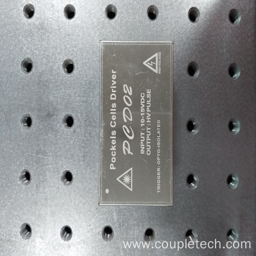
Our series of high-quality products represented by Q-Switch Pockels Cell Driver have become industry models, and buyers from all over the world are welcome to wholesale and buy!
Structural Principles
The composition of the Q drive
The Q driver consists of five parts: switching power supply, radio frequency unit, main control board, external interface, and control panel.
switching power supply
The switching power supply provides power to the radio frequency unit, and the input voltage of the switching power supply is AC220V±15% (it has been configured as one of them at the factory). The output voltage can be continuously adjusted between 7-14V. The level of the output voltage directly determines the output RF power of the RF unit, so adjusting the voltage value can adjust the RF output power.
The magnitude of the RF power output by the Q driver directly affects the performance of the Q switch. If the RF power is too small, the laser power that can be turned off by the Q-switching element is too small. If the RF power is too large, the laser power that can be turned off by the Q switch element increases, but the peak laser power output by the Q modulation decreases. Therefore, for different Q-switching elements and different applications, the output RF power should be adjusted to an appropriate value. Because the adjustment method of each company is different. Not much introduction here.
RF unit
To prevent leakage of RF interference, the RF unit is sealed in a metal box. It generates a radio frequency signal of 27.125M or 40M. And under the control of the main control board, the corresponding RF envelope sequence waves are output. Thereby, the operation of the Q switch element is controlled. When the radio frequency unit is overheated, the output terminal is short-circuited or open-circuited, it will output a protection signal to the main control board and drive the protection unit to act.
The center RF precision of the RF unit is very high, and the waveform distortion is small. Therefore, when driving a pure negative 50 ohm Q switch element. The electrical parameters are well matched and the VSWR is small. However, if the wave impedance of the Q-switching element has an impedance value deviation from the pure resistive Ω, the RF reflection and standing wave ratio will become larger, and the wave impedance of the Q-switching element must be adjusted to match the driver, otherwise, the RF reflection will be too large. , will damage the drive
main control board
The main control board is the control center of the driver, including four parts of circuits including control power supply, modulation pulse generation, control mode and protection logic. It accepts the signals from the panel and the external control interface, controls and protects the work of the radio frequency unit, and at the same time it outputs the status signal of the driver to the panel and the external control interface.
control power
The control power supply is a switching power supply with four sets of outputs. It provides ±15V, -15V, +5V, +12V four groups of working power to the main control board.


